Human Pose Estimation - Recap and Dataset Generation
Recap
Human pose estimation is the process of determining the pose of humans in a scene, usually using a standardized skeleton with pre-defined joints. My algorithm calculates the position of each joint in 3D space by optimizing the 3D coordinates of each joint. The optimization is a function of the difference between the detected 2D joint and the projection of the 2D joint for each image. This process works for any number of cameras and 2D detectors.
Previously, I tested this algorithm with simulated data and real data, using the Human 3.6M and MPI-INF-3DHP datasets. I used both Mediapipe and OpenPose as 3D detectors. The results from Mediapipe were more promising than OpenPose's. Nevertheless, there was always a problem of evaluation when using those detectors because the available skeleton formats didn't match the skeleton formats used for the dataset's ground truth skeletons.
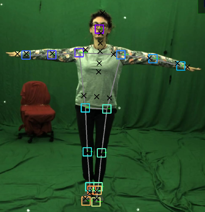
Using the following image as an example, where the black crosses represent the dataset of 2D ground truth poses and the colored squares represent the 2D detections by Mediapipe, we can see that the joint correspondence between ground truth and detector is not correct. For example, MediaPipe "sees" the hip points much lower than where the groundtruth places them, and MediaPipe doesn't even have spine joints, while the groundtruth does. This discrepancy was the main concern from the beginning because it makes evaluation almost impossible.
From now on, I will use as an example the same 10 frames from the MPI-INF-3DHP dataset.
The following table shows the MediaPipe detector 2D errors in pixels for those 10 frames. Here, I choose just the better-suited joints, that is, arms and legs. As we can see, frame errors are above 25 pixels, and even the best joints have almost 10 pixels of error.
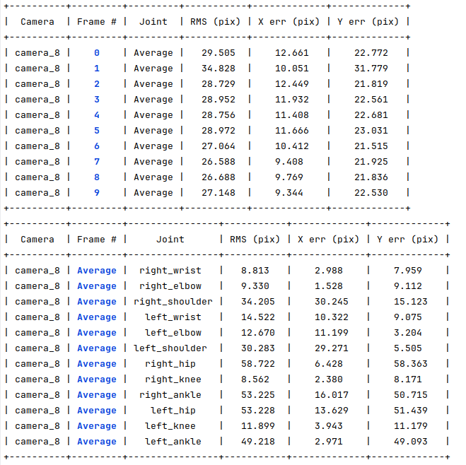
As discussed earlier, these types of errors will be propagated into the 3D poses, and as we cannot truly compare the skeletons because they are of different formats, we have no way to determine whether the HPE error comes from badly optimized skeletons or a fixed error caused by this discrepancy.
The solution to this problem was to use the groundtruth 2D poses as the input for the optimization,which has the exact same skeleton as the 3D groundtruth and therefore allows for a true comparison of the obtained results. Obviously, I cannot truly evaluate the performance of the algorithm with a perfect input (as the 2D groundtruth is), so the idea was to create a groundtruth tampering tool to generate comparable datasets with occlusions and errors.
Dataset generator
What I call a dataset generator is simply a tool that reads the 2D groundtruth for the requested dataset and tampers the dataset to create joint errors and occlusions. This tool has two functioning modes: a manual occlusion generation tool, where you can manually eliminate from each image arms and legs; and a random generation functionality, where the user inputs the maximum pixel error and the maximum number of occlusions per image, and occlusions and errors are generated accordingly. The user can also define the number of frames that the dataset will have and which cameras will be affected.
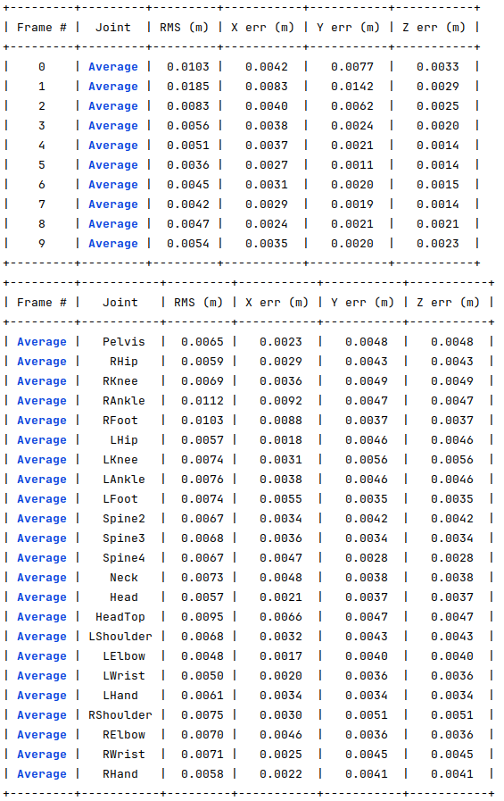
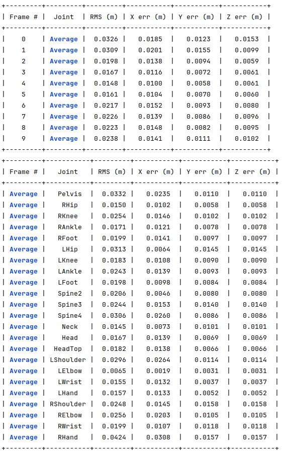
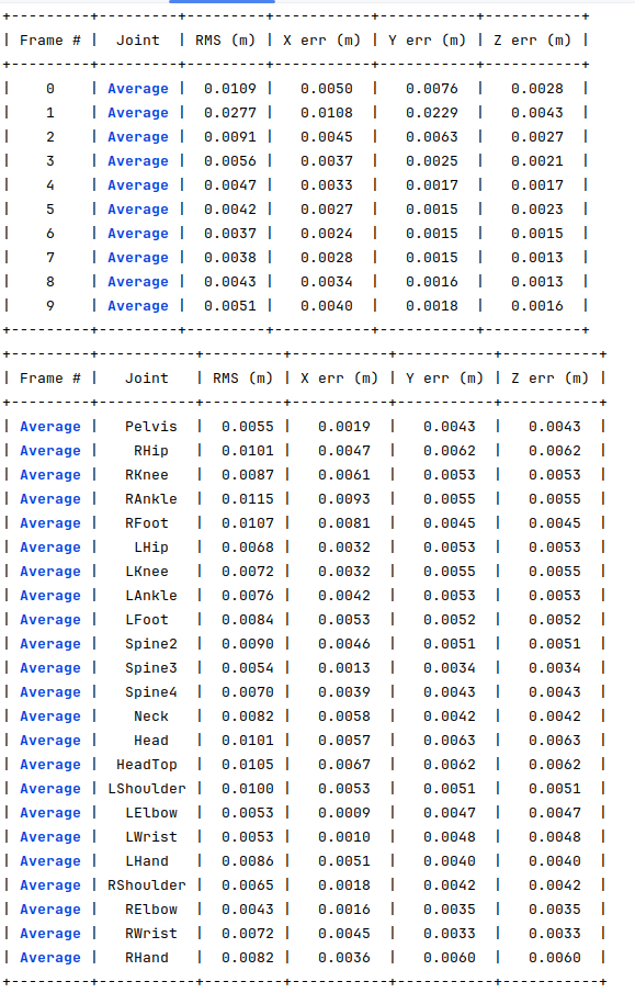
For the same 10 frames mentioned before, I use the dataset generator to create a new dataset where 30% of the joints have 10 pixels of error and a maximum of 3 occluded joints, where the obtained optimization errors are shown in the following image. For almost all the joints, the results were below 1 cm of error, which is very accurate.
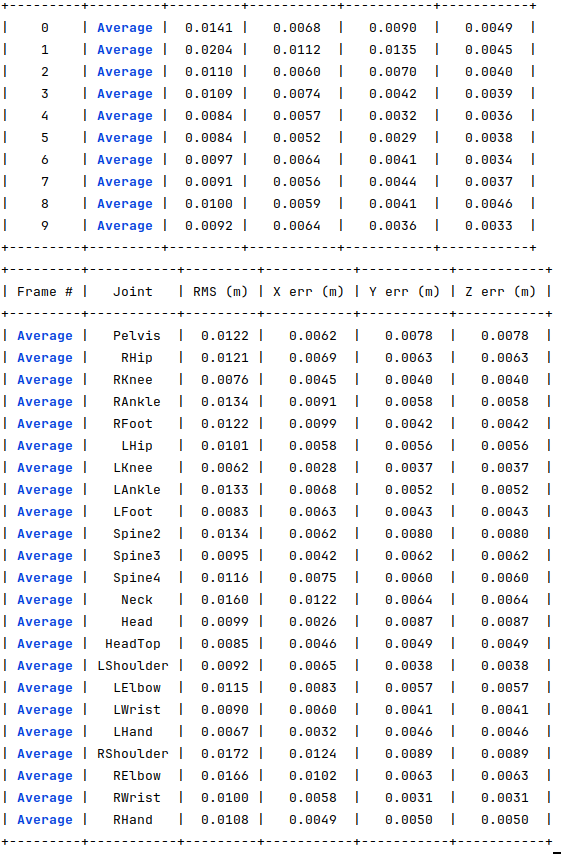
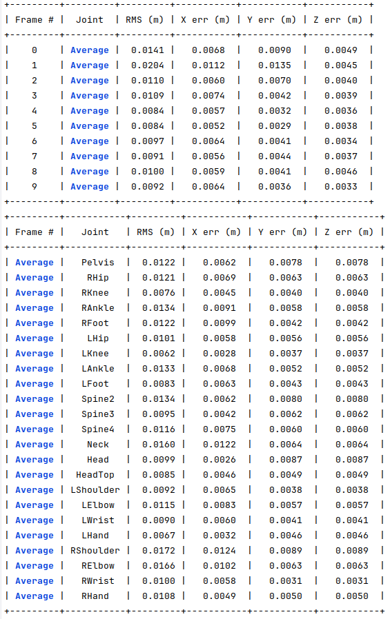
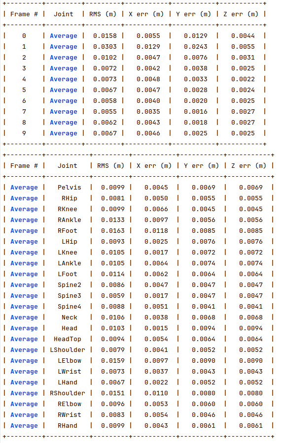
For the same 10 joints, I generated another dataset where 30% of the joints have 25 pixels of error and a maximum of 3 occluded joints. The following image shows the obtained errors. For all the joints, the errors are around 1 cm, which is still very low.
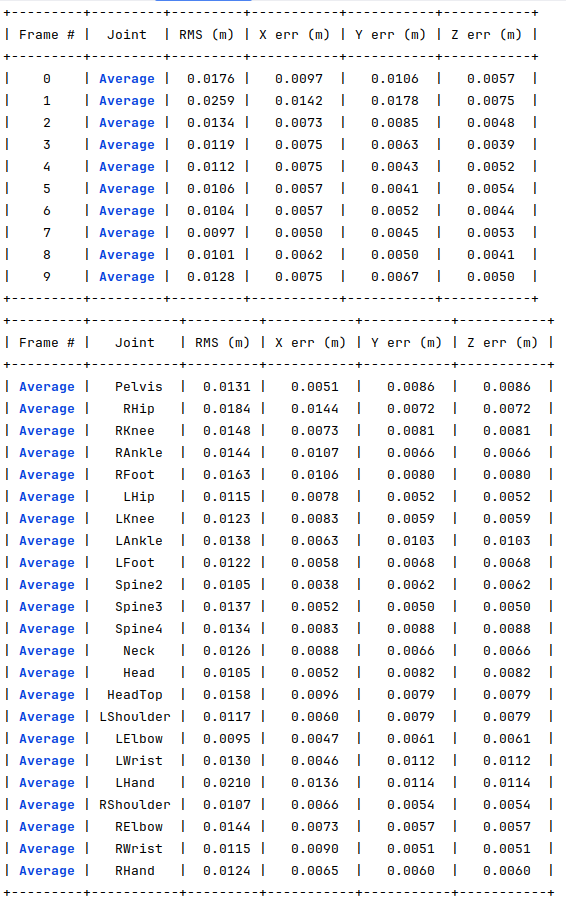
For the same 10 joints, I generated another dataset where 30% of the joints have 50 pixels of error and a maximum of 3 occluded joints. The following image shows the obtained errors.
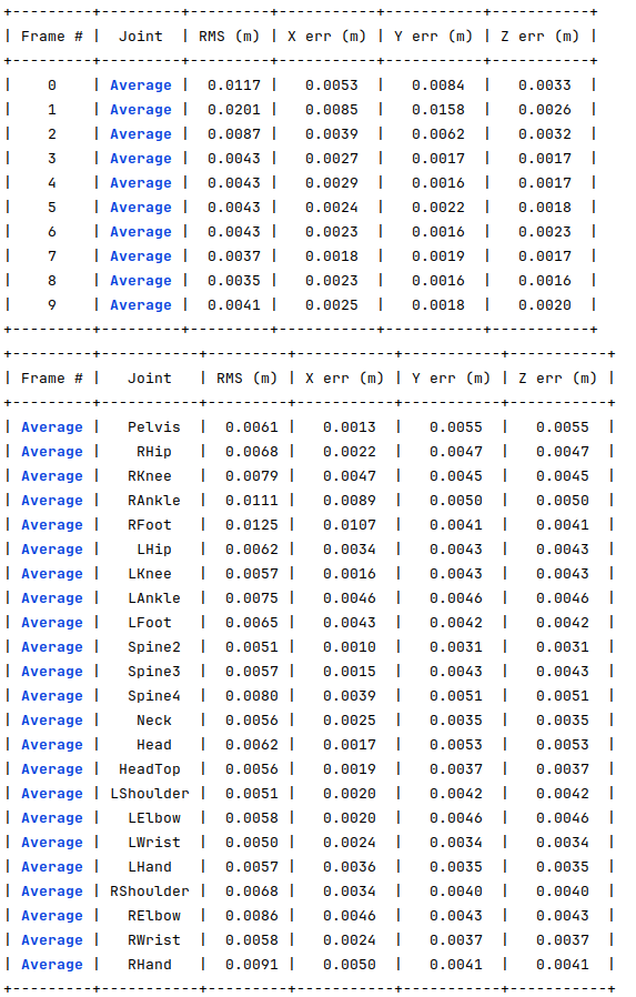
For the same 10 joints, I generated another dataset where 50% of the joints have 10 pixels of error and a maximum of 3 occluded joints. The following image shows the obtained errors.
For the same 10 joints, I generated another dataset where 100% of the joints have 10 pixels of error and a maximum of 3 occluded joints. The following image shows the obtained errors.
For the same 10 joints, I generated another dataset where 30% of the joints have 10 pixels of error and of 7 occluded joints. The following image shows the obtained errors.
For the same 10 joints, I generated another dataset where 30% of the joints have 10 pixels of error and of 12 occluded joints. The following image shows the obtained errors.
For the same 10 joints, I generated another dataset where 30% of the joints have 10 pixels of error and of 18 occluded joints. The following image shows the obtained errors.
In conclusion, this allows us to understand that algorithm is working correctly and perform an infinite number of experiments and even evalute how the increase in errors and occlusion really impacts the performance of the HPE algorithm. It also allows us to compare our results with other works that use the same datasets.
Issues of the month
- Results for 10 frames - open
- Link length residuals are hurting optimization - open
- How to name new 2d pose files with generated errors/occlusions? - open
- Generate random joint 2D detections errors and occlusions in 2D grountruth - open
- Optimize joint values instead of X,Y,Z coordinates - open
- Ground truth for some datasets has the axis switched. How to detected which axis is the floor to transform the points? - open
- Visualization not showing occluded joints that are later detected by optimization - open
- Create versions of 2D ground truth with noise and occlusions - open