Calibration of LarCCell
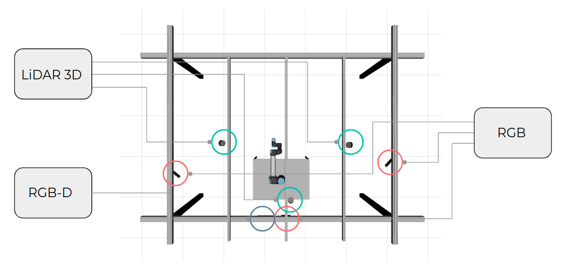
LarCCell is a collaborative cell that serves as a case of study for this project. The ultimate goal is that it becomes a tridimensional space where it is safe for robots and humans to cooperate and perform common tasks. To achieve this goal, it is necessary to have a great abundance of sensors to monitor the space and to have redundancy to foresee occlusions. The current setup of LarCCell is shown in the following image.
To create a controlled environment and to have a "ground truth" to compare our real results, a simulation of our collaborative cell was developed to mimic the real cell that is installed in our laboratory. The following video shows a simulation of our current setup.
The calibration of Larcc was done both in the simulated and real environment. The simulation serves as a base, because the position of the sensors is precisely known and the calibrated position can be compared with the actual position of the sensors, and we can evaluate whether our system is behaving the way it was supposed to. For this, we needed four datasets: a train and test dataset for real world, and the same for simulation. The train dataset is used to do the actual calibration, and the test dataset serves to run the evaluation metrics: the calibrated transformations are applied to the test dataset collections, that have the sensors in the same position as the train dataset, but different collections and calibration pattern positions.
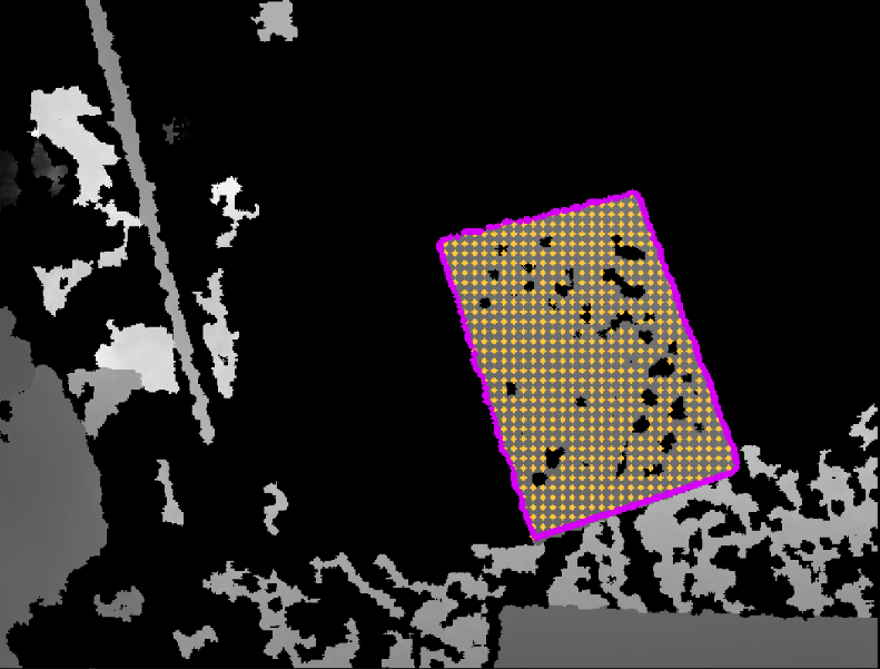
As mentioned in previous posts, to calibrate Larcc it was necessary to add the depth camera to ATOM framework. The automatic labeling of this camera was developed with a tetra-directional propagation algorithm. The propagation happens from a seed points that is initially manually given, and then it is updated from frame to frame by assuming that the centroid of the chessboard in the depth image is still inside the chessboard in the next frame. Overall this works well but sometimes it is necessary to manually readjust its position. The following image shows an example of a labeled depth image. This labeling is divided in limit points (purple points) and inside points (yellow points).
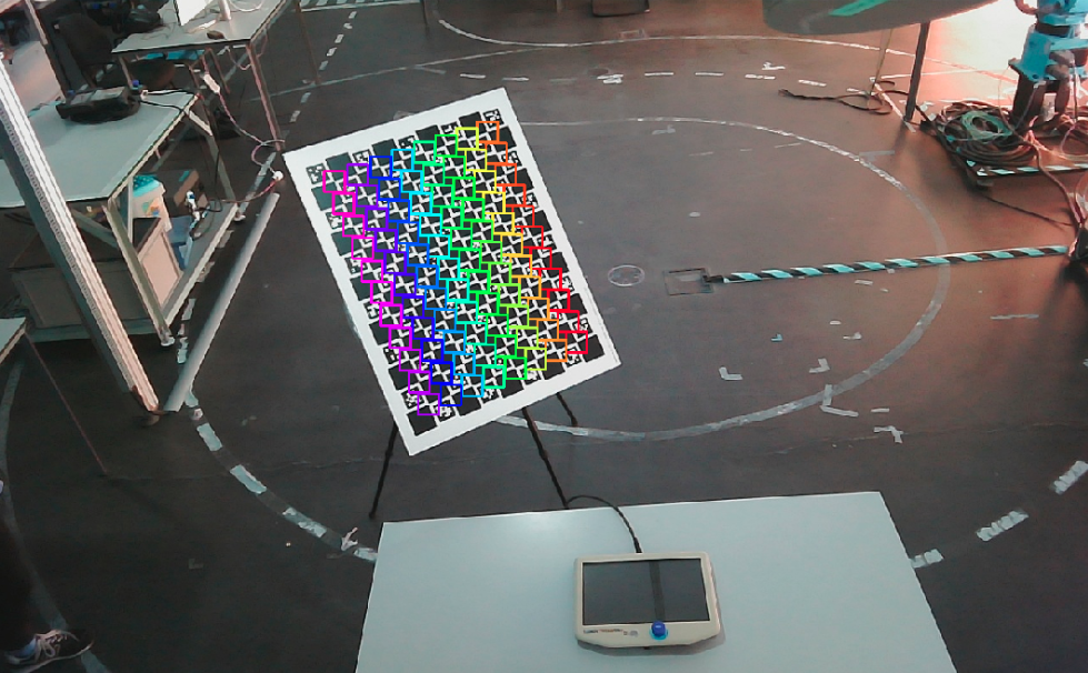
The following images show RGB and LiDAR labels in the real larcc.
Manual Labeling
We noticed that there were being some problems with the LiDAR and depth labeling in the real data because nearby objects often confuse the automatic algorithms. Even small errors can have a huge impact on the calibration accuracy, so these labeling issues had to be addressed. For this, we developed a dataset reviewer, that loads the dataset and allows to manually correct both LiDAR and depth labelling to obtain more accurate results. The following video shows an example of the utilization of this dataset reviewer.
Calibration
The calibration framework was overall maintained except for the added depth camera. To calibrate the depth camera the philosophy was similar to the LiDAR: the inside label points were used to calculate the ortogonal error between the pattern and the depth projection and the limit labels were used to calculate the longitudinal errors. The main difference between these methodologies is that LiDARs already give us tridimensional points, and depth give us (x_pix, y_pix) and a distance value. So these values need to be converted using the pinhole camera model and by knowing Z (the value of the pixel in a specific coordinates) and we can obtain the real X,Y,Z coordinates.
So far, all the calibration tests performed in real world datasets retrieved from different bagfiles showed promising results with sub-pixel error for RGB cameras and milimetric error for LiDARs and depth cameras.
The following video shows a demonstration of the calibrate collaborative cell in real world.
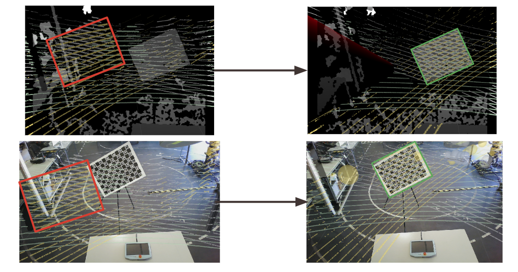
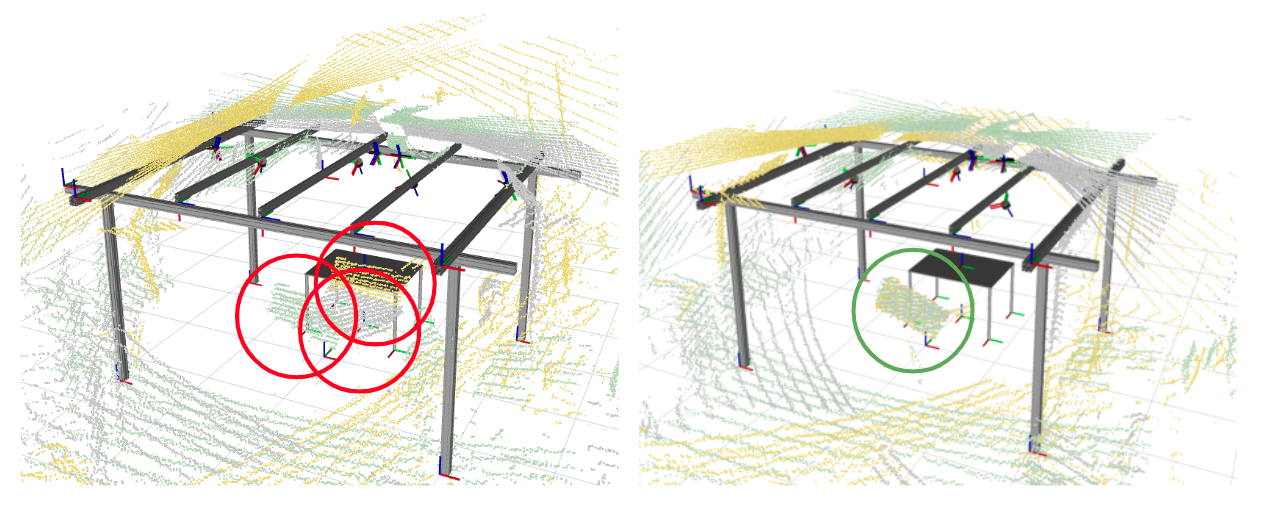
The following images show the difference between calibrated and uncalibrated data.
Other problems solved
- Fixed saved depth images with wrong file type that was causing deformed and unreadable datasets.
- Fixed calibration disparity between anchored LiDAR sensors and other sensors (calibration was giving less weight to the anchored sensor due to being a LiDAR and having lower errors than cameras)
- Fixed script for inspecting the dataset (was not working when the first collection had no detection)
- Fixed calibration script (was not working when it had only one collection and one of the sensors had no detection)
- Added the launch file generation for the dataset playback (reviewer)
- Added depth image visualization to both the visualization function of the calibrator and the dataset playback
- Added chessboard projections to the depth image when calibration to able the visualization of the progress of calibration
- Added option to input different configuration files when configuring the calibration package
- Fixing calibration errors of anchored LiDAR
- Removing depth limit labelling of image limits
TODO
- Obtain qualitative results on the larcc calibration in real data
- Obtain qualitative results on the larcc calibration in real data
- Compare obtained calibration results with OpenCV pairwise calibration for RGB cameras
- Compare obtained calibration results with ICP pairwise calibration for 3D LiDAR