Depth Modality Calibration
The process of adding the depth sensor to ATOM had two stages: collect data stage, which includes labelling, creating the dataset and saving the collection, and the calibration stage, which includes creating an objetive function branch for depth messages that outputs the residuals that are to be optimized.
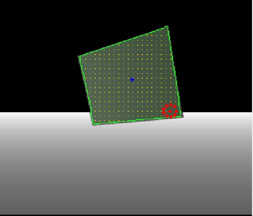
Regarding the collect data phase, we created a labeling methodology based on region growth. For this, we need to give the function a seed point, from which the function will propagate until a chosen threshold to find the limits of the calibration pattern. This seed points is initially given by an interactive marker in RVIZ that can be placed overlapping the pattern. In the following frames, the seed point will be automatically calculated by the centroid of the detected pattern in the previous frame, assuming that the pattern does not move fast enough that the centroid of the previous frame would not overlap the pattern in the current frame.
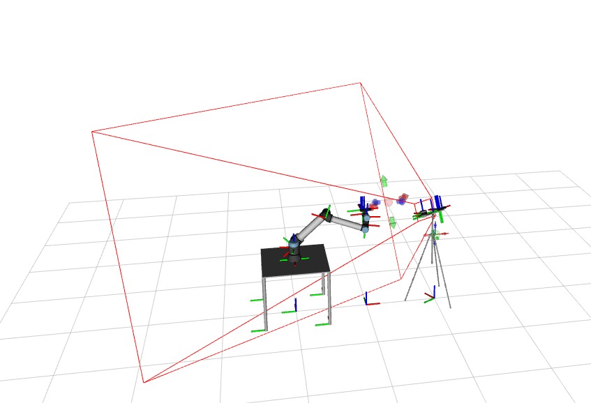
To facilitate the process of placing the interactive marker correctly, we added the visualization of the cameras's frustum to RVIZ, which allows us to see the 3D space covered by the camera.
After this process, the linear indexes of the detected points are stored in the dataset in two ways: the indexes of the limit points of the pattern and the indexes detected inside the pattern. The image is also store alongside the collection to visualize and later load the dataset information again.
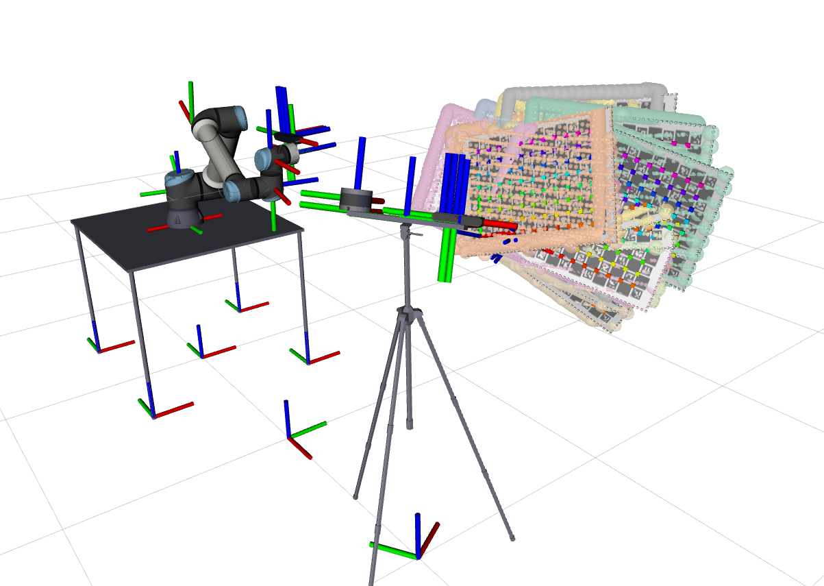
For the calibration phase, we need to load back the values of the detected points, whose indexes were previously stored in the dataset, and convert them to the camera coordinated system, in meters, using the camera pinhole model. This is possible because the Z coordinate is already known (its the value of the pixel in the image). By comparing these coordinates with the coordinates of the pattern in the camera's frame, we can obtain the orthogonal and longitudinal errors, that are used as residuals to optimize the calibration. The calibrator was also adapted to give the option of sampling the depth data to make the calibration faster.
TODO
- Improve calibration pattern support to improve the depth images detection
- Define solution to allow the robot to move the calibration pattern (robot assisted)
- Calibrate a system that includes a depth sensor
- Brainstorm about how are we going to calibrate the gantry with the sensors
Issues
Add depth component to ATOM's framework - open
Chessboard being poorly detected in RGB with lower resolution - closed
Check RGB header when loading json file - closed
Calibrating a simulated system with RGB, LiDAR and Depth - open
Calibration taking too much time between iterations - open
Create one file with a function for each component of the objective function. - open
Sample limit points in depth labeller - open
Create rgbd camera xacro which also has a visual component for the depth camera - open
Simulated experiment mmtbot calibration using only the rgb cameras - open
Verify that the sensor link frame id is the one in the header of the topic name message - open
Check if nig is being applied to the anchored sensor - closed
(opened but not this week's work)
Change resolution of astra camera to SXGA or XGA - open
Reduce camera frame rate in real time - open