Assembly of physical structure
Physical assembly of the structure including gantry, all the setup of the sensors (cameras and LiDARS), cabling, collaborative robot and connections to computer.Creation and adaptation of drivers for velodynes and cameras
The creation and adaptation of drivers is essential to ensure the communication with ROS. For the velodyne, this included using the ROS velodyne_driver. To communicate with different velodynes, it is necessary to connect them to a switch and define different IPs for each one of them.In the case of the astra cameras, there is also a ROS driver. Yet, this driver does not work well in multi camera mode due to USB overflow. Currently, this problem isn't yet solved because each USB camera requires a single unique USB port. Our efforts led us to conclude that our current computer is not able to handle this because of USB incompatibilities with the current motherboard.
Development of a fully simulated collaborative cell (larcc)
I developed a fully functional collaborative cell mimicking the real one at LAR. This involved the creation of xacros for each cell component. It also involved the simulation in gazebo of the cameras, lidars and collaborative robot.At the moment, the cell is completly working in real time and is able to simulate all of the above and to plan and execute ur10e trajectories using the motion planning toolbox.
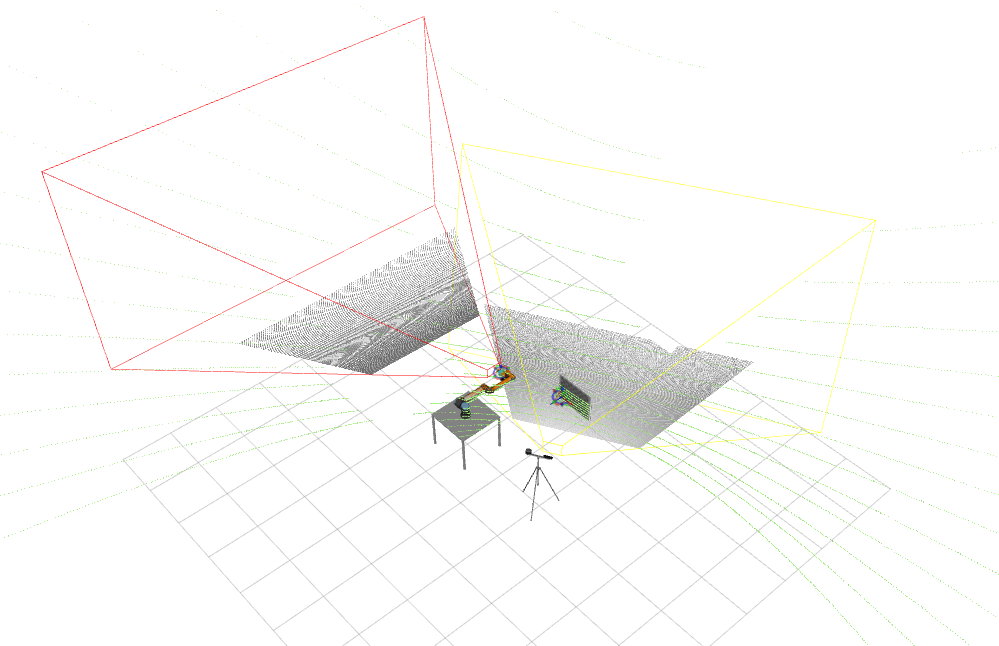
 Several tests of the sensor drivers (Orbecc Astra and Velodyne VLP16) were performed to obtain robust communication with the sensors through the ROS. These tests also implied adapting the drivers to work with multiple sensors simultaneously. It is now possible to acquire sensory data from the 3D lidar and the RGBD cameras. Experiments are being conducted to understand the number of sensors that can be used simultaneously. To optimize the bandwidth used for communications between sensors and the computer, the sensors are being configured to the appropriate resolution in the case of the cameras. The lidars are being configured to monitor of a 180º spherical calotte instead of the 360º configured by default. The following figure has an example of sensory data visualized in real-time in the cell. The video can be viewed at https://www.youtube.com/watch?v=miV3Ge0ebUw .
Development of a tool to visualize the sensors' frustrum
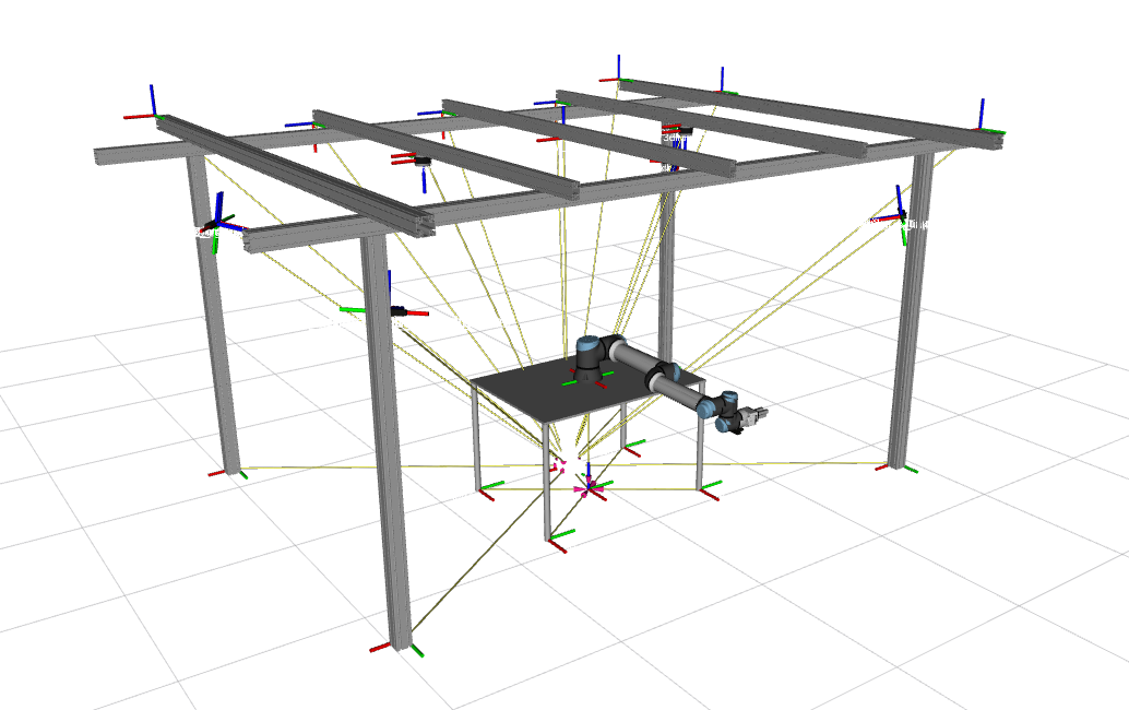
An interactive system is being developed to support the optimization of the positioning of the sensors using real-time visualization of their field of view. This tool selects the ROS topics corresponding to the cameras connected at the moment. It can fetch the necessary parameters of the camera pinhole model, such as focal length and image size, from the camera information published by the driver. From these parameters and knowing the minimum and maximum plane of cut corresponding to the sensor, mathematical equations are used to calculate the size of the sensor frustum. This frustum allows knowing exactly the field of view of each sensor and is drawn in real-time in the ROS visualization tool, RVIZ. This tool, shown in the following figure, is considered fundamental to determining the sensors' optimal positioning that results in the largest possible covered cell volume, which is essential to ensure that the safety requirements involved in human-robot collaboration are met.